Pinout
- This page lists the pinout of the FLY-F407ZG motherboard after flashing Klipper firmware. Pin numbers are based on the motherboard schematic.
UART/CSis the driver communication pin: used as UART with TMC2209, and as chip selectCSwith SPI drivers such as TMC5160. The same pin is shared between these functions.ENis the enable pin, typically active-low in Klipper configuration (prefixenable_pinwith!).- The driver sockets on the FLY-F407ZG do not provide a DIAG mapping that can be directly used for Klipper sensorless homing. The regular IOs listed below are for endstops or general inputs only.
Interactive Pin Hotspots
The image below uses the FLY-F407ZG product image and the same hotspot data from the Klipper configuration generator. Use the device filters above to show only compatible connectors; click a hotspot to see compatible devices, common Klipper configuration sections, and notes. Use “Locate in pin table” in the detail panel to jump to and highlight the corresponding row below. Hover still shows the connector name and pin. Always verify the silkscreen and connector positions against the physical board and schematic.
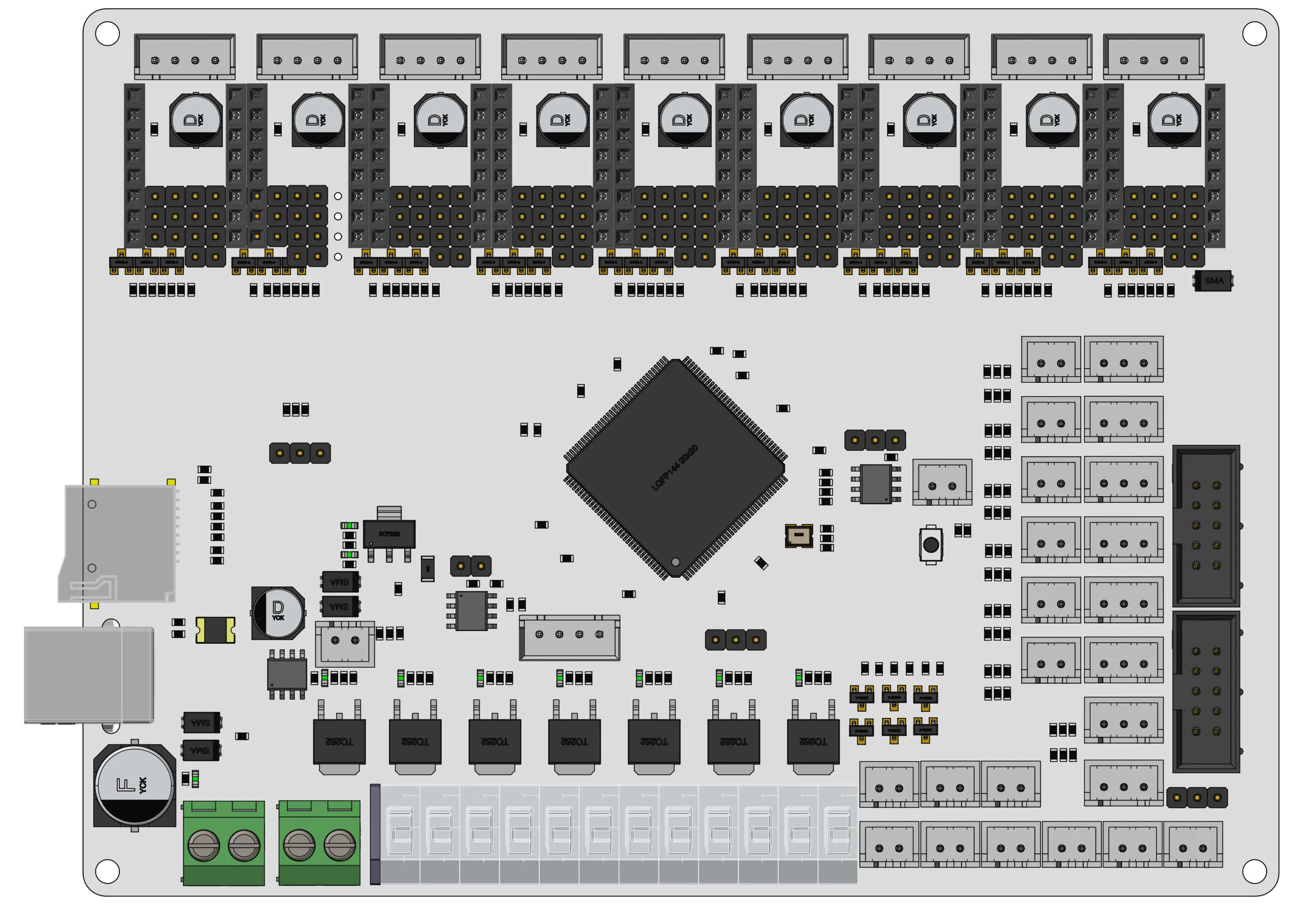
Hover to see the pin; click a hotspot to view compatible devices and configs. Pins can be copied from the detail panel, except for driver connectors.
Driver Pins
The FLY-F407ZG provides 9 driver sockets:
| Driver | STEP | DIR | EN | UART/CS | DIAG |
|---|---|---|---|---|---|
| DRIVER0 | PB9 | PE0 | PE1 | PG13 | - |
| DRIVER1 | PB8 | PG11 | PG12 | PG10 | - |
| DRIVER2 | PA8 | PD6 | PD7 | PD5 | - |
| DRIVER3 | PC7 | PD3 | PD4 | PD1 | - |
| DRIVER4 | PC6 | PA15 | PD0 | PA14 | - |
| DRIVER5 | PD15 | PG7 | PG8 | PG6 | - |
| DRIVER6 | PD14 | PG4 | PG5 | PG3 | - |
| DRIVER7 | PD13 | PD11 | PG2 | PD10 | - |
| DRIVER8 | PD12 | PD8 | PD9 | PB12 | - |
Before starting, completely shut down the printer and disconnect the power supply. Do not plug or unplug wiring harnesses, organize interface wiring, or touch terminals while the power is on.
Neither the pinout diagram nor the reference configuration for the FLY-F407ZG provides a mapping from the driver DIAG pins to the MCU input pins, so DIAG remains - in the driver table.
The IO0-IO7 pins listed below are independent regular endstop / general input pins, not driver DIAG signals. When configuring Klipper, do not use these regular IOs directly as diag_pin for any driver.
SPI Bus
SPI drivers such as the TMC5160 use the motherboard's hardware SPI bus. Configure spi_bus: spi1a in the configuration, with no need to configure MOSI/MISO/SCLK pins separately:
[tmc5160 stepper_x]
spi_bus: spi1a
cs_pin: UART/CS pin of the corresponding driver
Detailed information on software SPI and SPI speed: SPI Configuration Method
Endstops and Probe
| Function | Pin | Corresponding Driver DIAG |
|---|---|---|
| Endstop Port 0 / IO0 | PC3 | - |
| Endstop Port 1 / IO1 | PC2 | - |
| Endstop Port 2 / IO2 | PF2 | - |
| Endstop Port 3 / IO3 | PF1 | - |
| Endstop Port 4 / IO4 | PF0 | - |
| Endstop Port 5 / IO5 | PC15 | - |
| Endstop Port 6 / IO6 | PC14 | - |
| Endstop Port 7 / IO7 | PA3 | - |
For wiring of micro switches, optical endstops, proximity sensors, and TAP, see: Endstop Wiring Guide
Heaters
| Function | Pin |
|---|---|
| Heated Bed Heater | PE2 |
| Heater Port 0 | PF7 |
| Heater Port 1 | PF6 |
| Heater Port 2 | PE6 |
| Heater Port 3 | PE5 |
| Heater Port 4 | PE4 |
| Heater Port 5 | PE3 |
Temperature Sensors
| Function | Pin |
|---|---|
| Heated Bed Thermistor | PF3 |
| Thermistor Port 0 | PA0 |
| Thermistor Port 1 | PC1 |
| Thermistor Port 2 | PC0 |
| Thermistor Port 3 | PF10 |
| Thermistor Port 4 | PF5 |
| Thermistor Port 5 | PF4 |
The thermistor ports support NTC thermistors (100K) by default, with sensor_type recommended as Generic 3950; they also support 2-wire PT1000, configured by setting sensor_type to PT1000.
List of
sensor_typeoptions that can be directly connected internally by Klipper and their applicable scenarios: Thermistor Configuration Method
K-type thermocouples, 3-wire PT100, etc., require additional signal conditioning chips and cannot be connected directly to the thermistor ports.
Fans
| Function | Pin |
|---|---|
| Fan Port 0 | PF8 |
| Fan Port 1 | PF9 |
| Fan Port 2 | PA2 |
| Fan Port 3 | PA1 |
| Fan Port 4 | PE13 |
| Fan Port 5 | PB11 |
PWM
The FLY-F407ZG provides 1 PWM output, which can be used for servos, fan speed control, etc.:
| Pin | Remark |
|---|---|
| PE11 | Servo / BLTouch control |
EXP Interface
- EXP headers are commonly used for Mini12864 and other displays or expansion peripherals.
- If a pin is already occupied by SPI, UART, endstop, fan, or other functions, do not configure it again for EXP peripherals.
EXP1
| Function | Pin |
|---|---|
| EXP1_1 | PB10 |
| EXP1_2 | PE15 |
| EXP1_3 | PE14 |
| EXP1_4 | PE12 |
| EXP1_5 | PE10 |
| EXP1_6 | PE9 |
| EXP1_7 | PE8 |
| EXP1_8 | PE7 |
| EXP1_9 | GND |
| EXP1_10 | 5V |
EXP2
| Function | Pin |
|---|---|
| EXP2_1 | PB14 |
| EXP2_2 | PB13 |
| EXP2_3 | PC5 |
| EXP2_4 | PF11 |
| EXP2_5 | PC4 |
| EXP2_6 | PB15 |
| EXP2_7 | PB2 |
| EXP2_8 | RST |
| EXP2_9 | GND |
| EXP2_10 | NC |